|
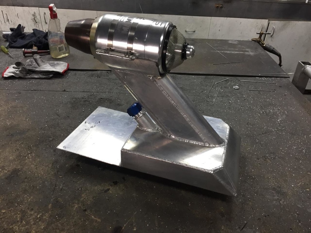
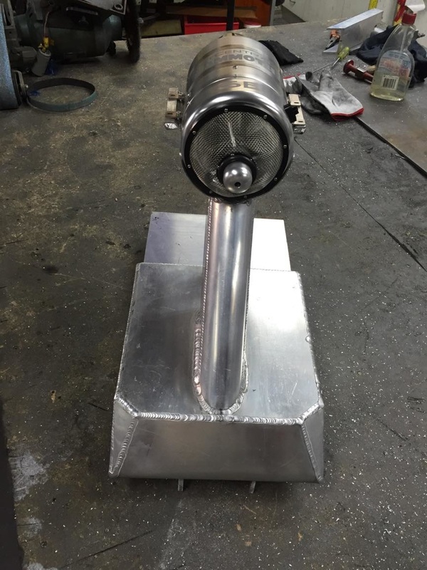
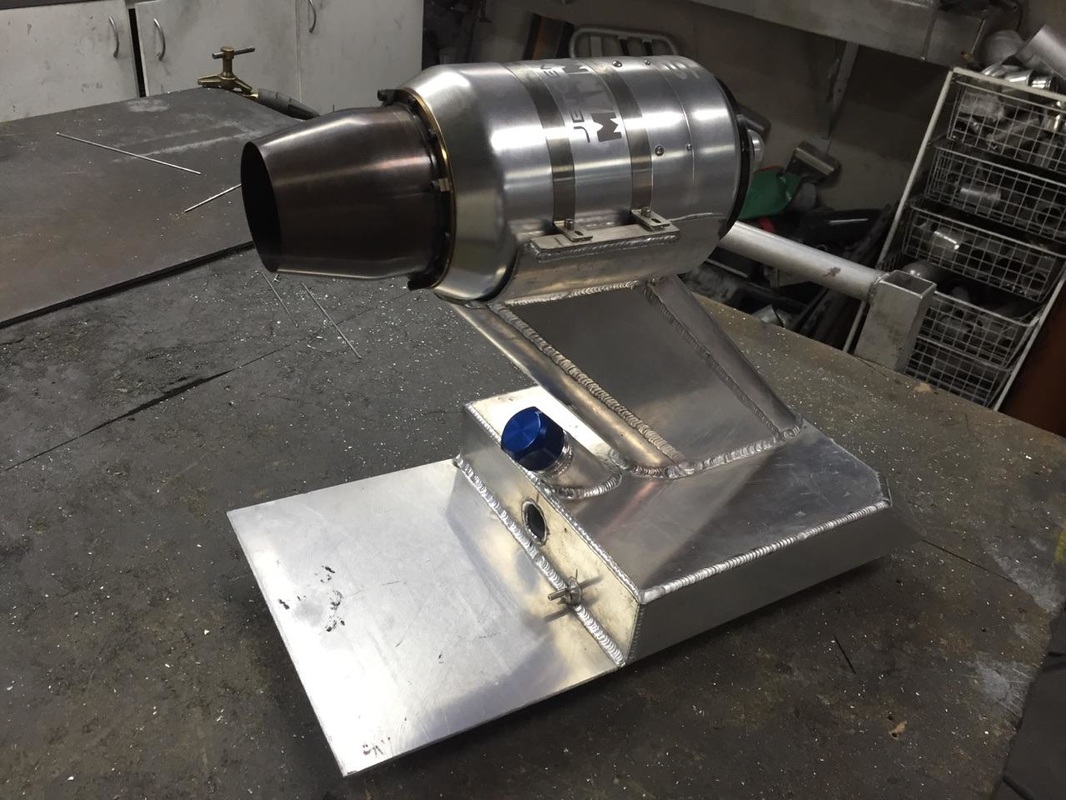
One of the most exciting moment in my life was receiving my new turbine. knowing i can finally get back to focusing on trying to break the landspeed record again and building the board to do it. the second most exciting thing was getting pictures of my nearly completed fuel tank on my birthday. below i will run you through the pictures and my design to give you a little understanding as to what i want to achieve with the board. 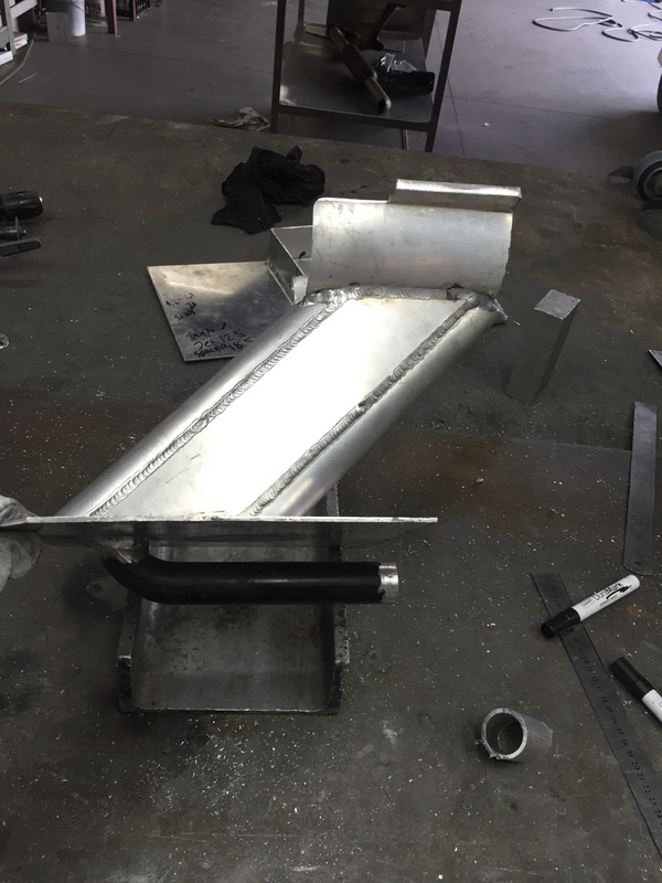 the is what we have been calling the tower. the turbine will sit at the very top. the bottom with the pipe will be the top of the fuel tank. the pipe will run through the tank and carry my electronics and fuel lines to the turbine. i wanted to the turbine to sit in the wind to offer best intake with minimal turbulence with a hope it will give me access to most of its power. 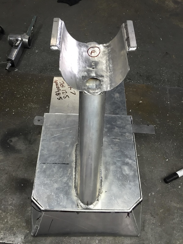 This is how the tank will look in completion. you can see in the top of the cradle where the fuel lines and electronics will meet the turbine. the two smaller holes at the rear are the breathers for the fuel tank. the F is for fun. 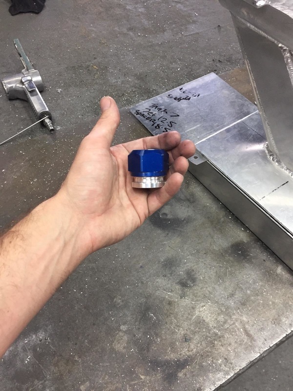 Only decision now is where do we put the fuel cap. you may note the overhang of alloy at the back of the fuel tank. this will be to lay out the electronics and fuel pump and computer. not sure how much space i'll need yet so we allowed enough to be able to cut it back later. 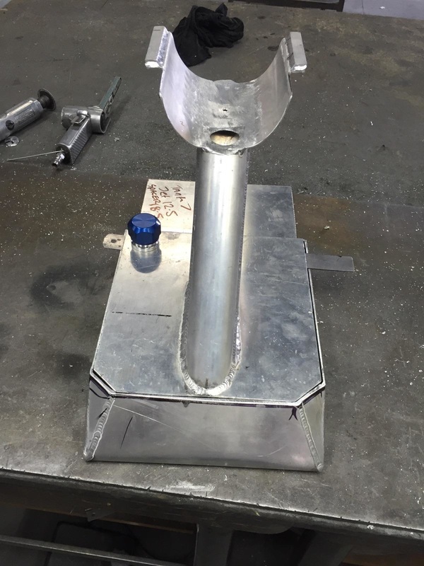 While this position make for easier refueling and convenience. it does look bloody stupid. it wasn't till i saw the next photo i knew where it had to go. 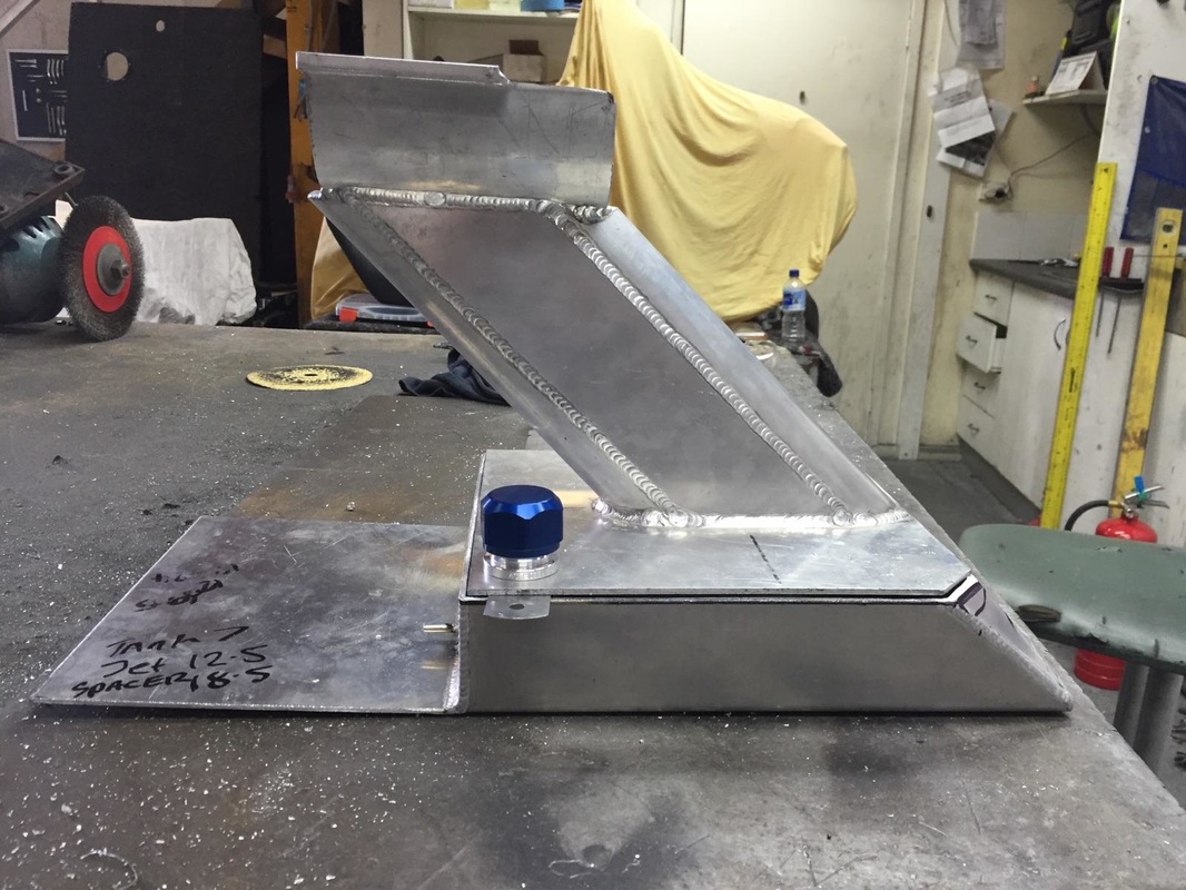 The moment i saw this image i knew what i had to do. but how to get the fuel cap behind the tower and still be able to access it? easy! You can also see the little fuel pickup pitot tube just below the fuel cap in this photo. for such a small tube this turbine apparently drinks allot of fuel. hence the tank size. when complete should be between 2.5 to 3 liters. 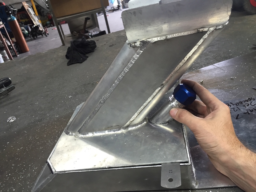 Nothing a bit of 2 inch alloy pipe can't fix and a 45% cut. this will be how everything mounts. now to just have it all welded up and we can get to fitting it on the board.
And just like that it was done. finally a completed fuel tank for the jet luge. Now it's time to get it back and mate it with the board. hopefully my measurements were correct and it will just slide together. Once i get it all mocked up i will start wiring to work out the layout for how things will go. i'm sure i'll be doing this more than just a couple of times. It's great to know after a long day's work you can come home to something you love.......and after spending time with my partner, i can go and play with the jet luge. i got word today that my spine and rear riser for the jet luge has been all welded up and is ready to go. that means i can finally put the rolling board together. the next thing i need done is the fuel tank. which should be done any time soon....ish. I gotta thank Hannah over at DIY Garage in Rutherford for the great work and speedy turnaround time on the welding. they have their grand opening on 9th of July. go say hi. 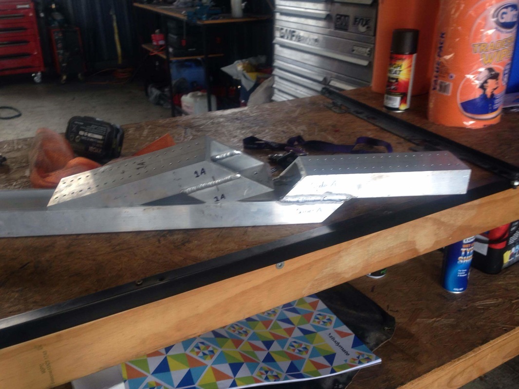 With the wheels of progress turning i continue to build and modify the new jet luge cannibalising part of the old. In this case, i refer to the forward controls. After the catastrophic failure of the last luge and with all the work put into it i couldn't bare to see it just sit there (don't worry i have plans for it also) Removing the forward controls i then had to mount them on the new board. it was rather straightforward considering i tend to use the same template for most of my boards. the hard part was the wiring. since the wiring for the new jet luge didn't correspond with the old boards setup.. the last setup was run on a 12v system. this new setup runs at 7.4v. this meant replacing the old potentiometer and replacing it with a compatible one.. A potentiometer is the (how fast do you want to go) bit of the the board. in this case very! you'll see the modifications and mounting of the forward controls in the pictures below. In this video i had just calibrated the throttle to the computer. this was not an easy task as the system was setup for more radio controls then highly modified streetlugers. 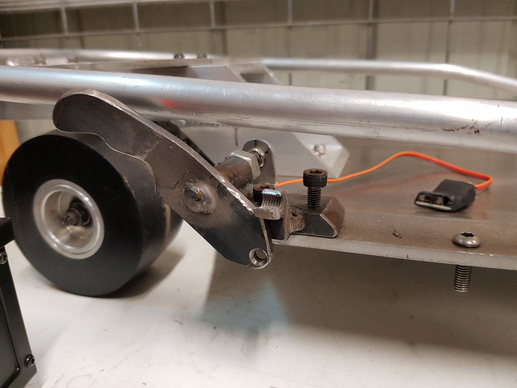 The next thing I had to do once it was rewired and roughly calibrated was get the thing mounted. The screw to the right of frame is to mount the return spring for the throttle. The second thing once i mounted it. i found i was not able to trim up and down properly and this would result in premature engine shut off. i need to get more throttle. the only way to do that was to shave down the original trim nut. This worked out well as i now had a very sturdy stop for when i reached full throttle. 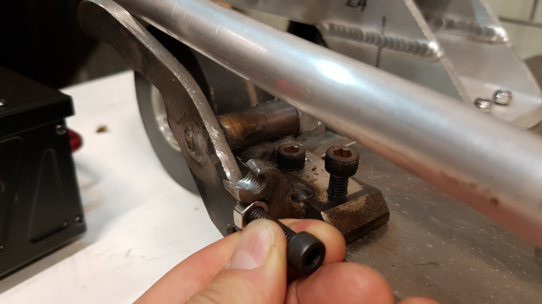 With the original trim nut now practically gone i was now forced to put the new trim nut underneath. this worked out extremely well as it actually allowed for more accuracy whilst trimming up and down. 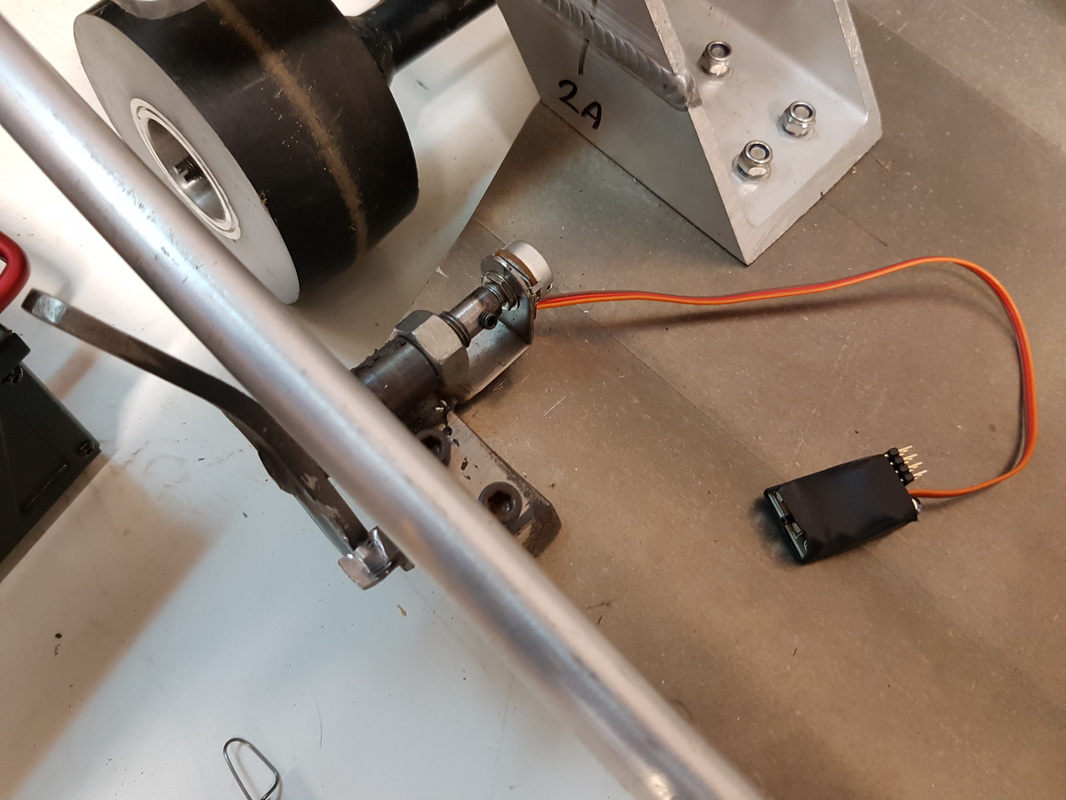 New pod modified wired and mounted. All set with a grub screw for a bit of security. the little black unit you see with the wires running to it was originally a servo tester i got off the internet. i modified it to run the new potentiometer. once all in place you will not see any of this wiring and most of it will be mounted and tucked away inside the center of the board. All working smoothly as you can see. this will be the setup for initial testing. i may refine whats been done but for the time been it seems to work just fine.
Now that i have the turbine, i can begin building. if you're counting, this will be. luge number 3. This board i want to keep as basic and simple as possible. i want it to stay as close to a competition board as i can. To do that, i have decided to take one of my best built boards and pull it apart. Just so i can build it back up again longer and hopefully faster. 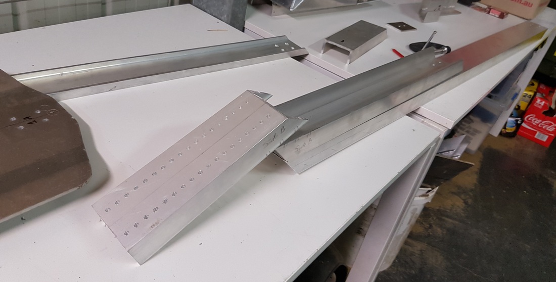 You will see in the photo above i will be extending the spine.. In doing this i will need to reinforcing the rail and doubling up on the channel to compensate for the extra length and weight. i will keep a bit of flex in the board for this one.. just a bit to keep things a little smoother over joints in the road and the odd stone on the track. 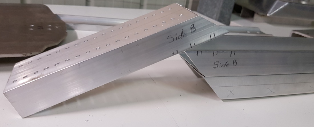 In the picture above you will see the markings i have made for the welder. i can't weld at home so i do this to avoid any confusion when i send it out. Match the lines on side A and side B and then weld. that simple. 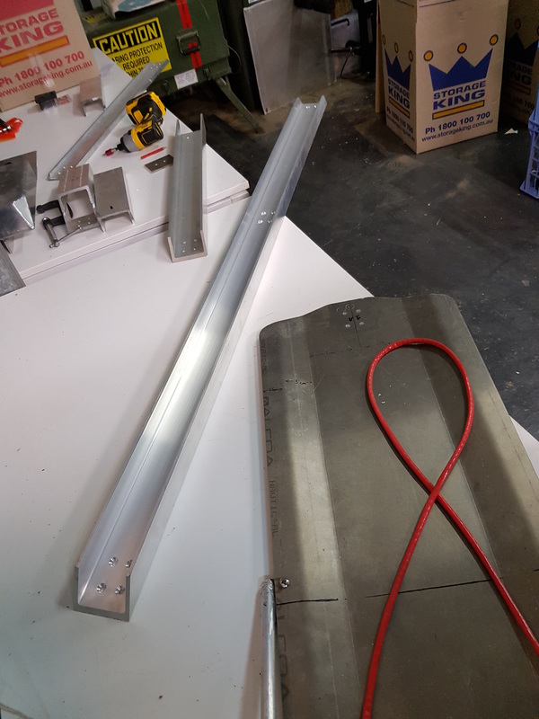 In this picture you can see the full length the new board will be. The 4 holes in the middle of the spine will match up with the holes in the pan next to it. the overhang at the rear will then run down to the riser with the turbine sitting in the middle.. i use T6 aluminum C channel for the spine and 6064 alloy for the pan. This is the same alloy i use in my race boards.
After a very very long wait. I have been putting every penny i could spare aside. Finally the beautiful shiny has arrived. I have been keeping it quiet. But this is what i have been saving for. My new turbine. Ready to mount and roll. Keep an eye on this blog as i have to build a new board from scratch for this turbine to go in. 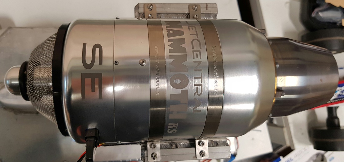 |

Partners:


Supporters:

Archives
August 2016
Categories
All
|


 RSS Feed
www.jetluge.com.au / CONTACT |
© Copyright JetLuge.com.au 2020-2027. All rights reserved.
|