|
With the wheels of progress turning i continue to build and modify the new jet luge cannibalising part of the old. In this case, i refer to the forward controls. After the catastrophic failure of the last luge and with all the work put into it i couldn't bare to see it just sit there (don't worry i have plans for it also) Removing the forward controls i then had to mount them on the new board. it was rather straightforward considering i tend to use the same template for most of my boards. the hard part was the wiring. since the wiring for the new jet luge didn't correspond with the old boards setup.. the last setup was run on a 12v system. this new setup runs at 7.4v. this meant replacing the old potentiometer and replacing it with a compatible one.. A potentiometer is the (how fast do you want to go) bit of the the board. in this case very! you'll see the modifications and mounting of the forward controls in the pictures below. In this video i had just calibrated the throttle to the computer. this was not an easy task as the system was setup for more radio controls then highly modified streetlugers. 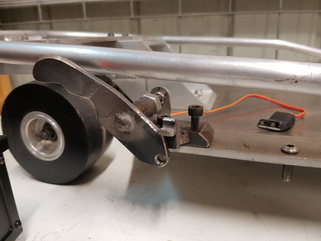 The next thing I had to do once it was rewired and roughly calibrated was get the thing mounted. The screw to the right of frame is to mount the return spring for the throttle. The second thing once i mounted it. i found i was not able to trim up and down properly and this would result in premature engine shut off. i need to get more throttle. the only way to do that was to shave down the original trim nut. This worked out well as i now had a very sturdy stop for when i reached full throttle. 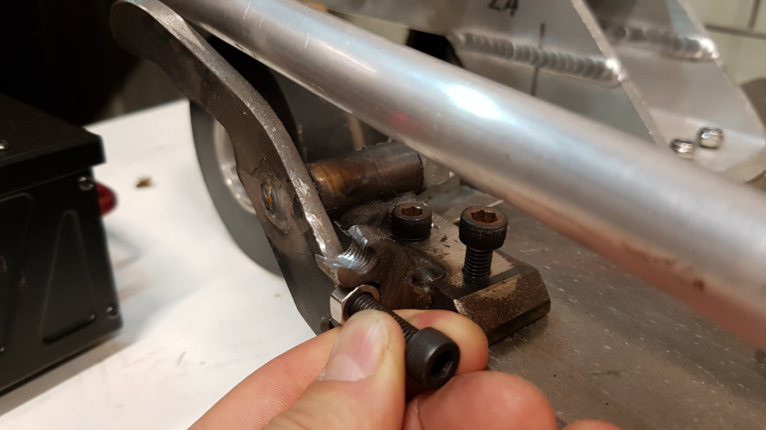 With the original trim nut now practically gone i was now forced to put the new trim nut underneath. this worked out extremely well as it actually allowed for more accuracy whilst trimming up and down. 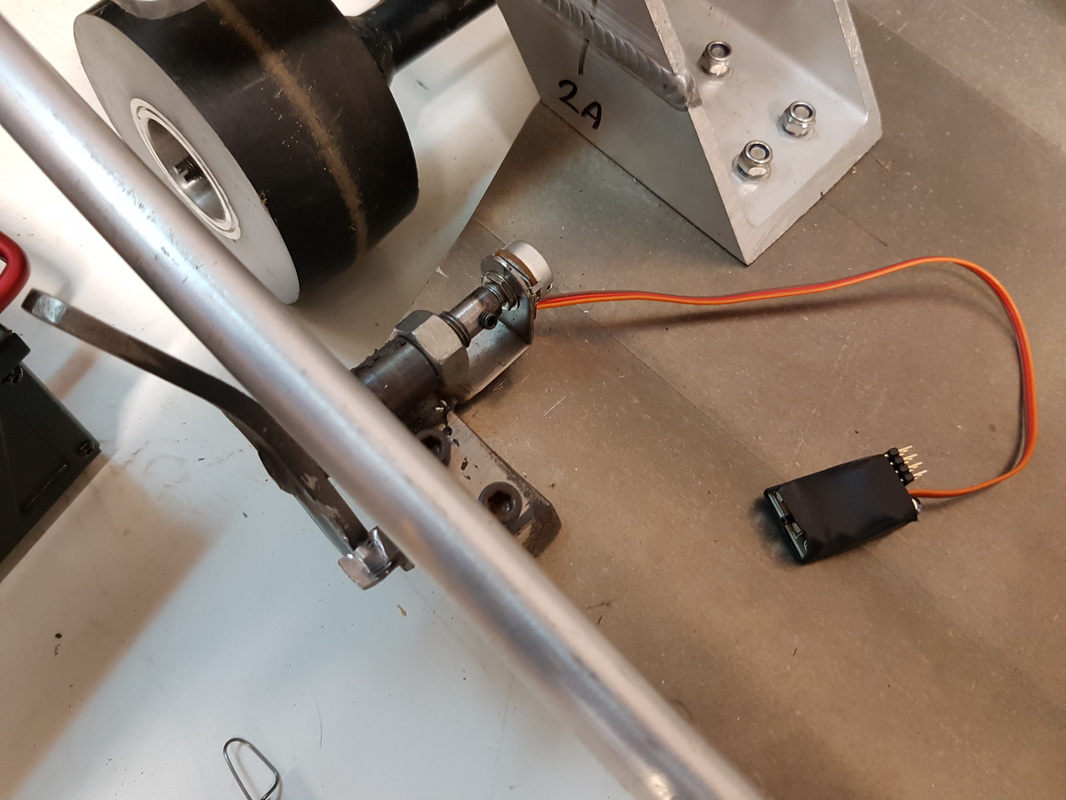 New pod modified wired and mounted. All set with a grub screw for a bit of security. the little black unit you see with the wires running to it was originally a servo tester i got off the internet. i modified it to run the new potentiometer. once all in place you will not see any of this wiring and most of it will be mounted and tucked away inside the center of the board. All working smoothly as you can see. this will be the setup for initial testing. i may refine whats been done but for the time been it seems to work just fine.
Leave a Reply. |

Partners:


Supporters:

Archives
August 2016
Categories
All
|


 RSS Feed
www.jetluge.com.au / CONTACT |
© Copyright JetLuge.com.au 2020-2027. All rights reserved.
|